
Model D33 Signal Conditioner
 The D33PM Series Signal Conditioner provides virtually all the standard features and many of the optional features of earlier single channel UD signal conditioners in a smaller chassis and at a lower total cost. Independent power supplies are used so that stand-alone operation, as well as multiple channel operation is possible. The power transformers are electro-statically and electro-magnetically shielded so that power frequency components are virtually absent in the output signals. Separable references for the input and output circuits allow an internal differential circuit to remove common mode ground voltages caused by grounding the transducer case at the point of measurement.
Download Instrumentation Bulletins
Overview
- .5 Digit LED meter for displaying peak sine and TRMS
- Operates with piezo accelerometers, remote charge pre-amps, single strain gages and self-amplified accelerometers
- Switchable 10, 100 mV/g (or mV/U) output for controllers
- Switchable four pole filtering
- Dial-A-Gain input sensitivity normalization
- High output current
- Low cost per channel
Front panel push-button controls and signal circuitry are contained on two printed circuit cards, which reduces internal wiring greatly and contributes to overall simplicity in layout.
Dial-A-Gain input sensitivity normalization, originated by UD, allows all outputs to be normalized for transducer sensitivities from 0.3 to 100 mV/unit, or pC/unit.
High frequency performance and slew rate performance have been improved to provide accurate high frequency shock measurements. Low frequency performance has also been improved to allow accurate measurements of classical shock tests. The droop in the measurement of the peak value of a 40 ms half-sine shock pulse is typically 5%.
Input signals are accepted by direct connection from piezoelectric accelerometers of force gages, or from accelerometers with internal amplifiers requiring two-wire constant current power source. The adjustable constant current source can also be used for exciting a single strain gage used for AC measurements.
Specifications
General
Enclosed modules with separate power supplies and rear mounted connectors.
Inputs
- Charge Input: Any single-ended piezoelectric transducer with shunt resistance as low as 10 kilohms - Source capacitance of 20 nF causes less than 1% gain change - Max. input 13,000 pC (1-10 pC/g); 130,000 pC (10-100 pC/g) at 45 kHz, 100,000 pC at 60 kHz.
- Voltage Input: Coaxial connection to a remote pre-amp/self-amplified accelerometer, or strain gage - Constant current internally adjustable from 1 to 20 mA - 25 VDC maximum compliance voltage.
- Calibration Input: External oscillator or internal 100 Hz oscillator (option O) - conversion constant 1 pC/mV for charge input calibration.
Outputs
- Ranged Output: Calibrated 0 to +/- 10 V pk output at full scale to 100 kHz; output impedance 10 ohms; +/- 35 mA maximum current.
- Servo Control Output: Selectable 10mV/g or 100mV/g unaffected by FS range switch; 3 pole Butterworth filtering +/-2% at 5kHz; output impedance 50 ohms maximum.
- Meter: 3 ½ digit LED meter with .5 inch numerals; decimal point automatically positioned; true rms detection; 3 pole averaging; +/- 1 LSD typical jitter at 2 Hz.; switch selectable for peak sine or true rms indication.
- DC-Output: 10.0VDC +/- 1% at full scale; response time is 1 s to 90% for step change in input; switch selectable for peak sine or true rms indication.
Input Sensitivity Normalization
Provided by a range switch (10 or 100 mV-pC/g max) and a precision 10 turn dial (actual ranges are 0.3 to 10.3 and 3 to 103 pC-mV/g). For dynamic (AC) strain gage inputs, input sensitivity is (gage factor) x (DC voltage across gage) in mV/1000µL.
Noise
- Charge Input: less than .004pC RMS plus .0012 pC/1nF source capacitance RTI plus 2 mV p-p RTO with 10 Hz. HPF and 10 kHz LPF (+/- 2% response).
- Strain Gage Input: less than 3µV RTI with a 120 ohm gage and 20mA current.
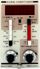
Front Panel Controls
- Input sensitivity range: 10 max, 100 max
- Input sensitivity vernier: 0.03 to 1.03 times max value (10 turn precision potentiometer and dial)
- Input selector: charge in-voltage in
- Filter switches (2): Out-In
- Case switch: Isolated-Grounded
- Mode switch: Operate-Calibrate
- Read bias switch (momentary)
- Adj. bias: multi-turn potentiometer
- Servo (mV/unit): 10-100
- F.S output dial: 0-10V pk (precision 10-turn)
- All push buttons are push-push operation
Physical
- Power: 105-125/210-250 VAC; 50/60 Hz
- Dimensions: 2.8"W x 5.25"H x 11.5"D with brackets suitable for mounting in a standard 19 inch rack.