
Transducer Calibration System
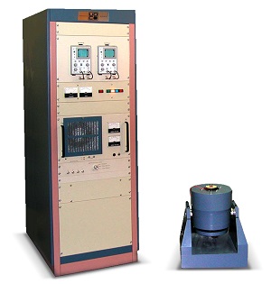
 Unholtz-Dickie Transducer Calibration Systems have earned their place in industry as the standard for calibrating accelerometers and velocity transducers. The Model 680C is UD's latest generation of an automated transducer calibration system, utilizing the expanded features of the i5 based APEX SL-C Windows vibration control system.
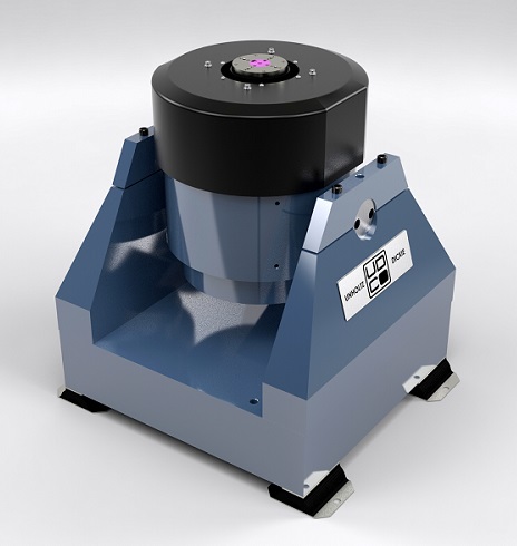
The Model 680C Calibration System offers a large 3.25 inch (83 mm) table and expanded performance envelope for high force, displacement and load capability. It is configured with the Model TA100CL-S032-C amplifier and shaker.
The Model 680C is a complete system and includes everything needed to calibrate accelerometers and velocity transducers, including the S032-C Calibration Shaker, Power Amplifier with integrated Field Power Supply, Cooling Fan, TSC-3 transducer signal conditioner, and 8B6 Lab and Working standard accelerometers and respective mounting hardware. The 680C is critical for satisfying ISO9000 test requirements of vibration transducers.
For U.S. NAVY applications UD supplies the Model 680 Transducer Calibration System. This is a customized version of the 680C with added features specific to the NAVY requirements.
Download Transducer Calibrator Bulletin
Calibration Certificates
Select the links below to view sample Calibration Certificates generated by the APEX SL-C calibration software. Note that custom certificates are available.
APEX SL Transducer Controller Provides:
 Fast computer-controlled calibration of accelerometers and velocity transducers
- Simple setup and definition
- Precise shaker control
- Reference & test transducer measurement
- Large data storage
- Automatic certification report
- Back-to-back accelerometer calibration method using NIST standard reference accelerometer
- Precision sinusoidal comparison technique
- Logarithmic sweep or stepped-frequency sine
- Wide frequency range of 2 to 10,000 Hz
- Wide acceleration range (0.1 to 75 g) with working standard and test accelerometer mounted
- Large mounting surface 3.25 inch (82.5 mm) diameter armature
- High velocity to 50 in/sec (1.3 m/sec)
- Accelerometer sensitivity 0.1 to 5,000 pc/g or mv/g
- Velocity transducer sensitivity 0.2 to 5,000 mv - sec/in
- Ceramic insert provides excellent stiffness, back-to-back mounting, rigid coupling to table, electrical isolation, and protection of working standard accelerometer
- Graphical spectrum display of sensitivity, deviation, control, reference and phase
- Tabular listing of selectable frequencies, sensitivities, and deviation
- Air-cooled power amplifier and shaker
- Heavy-duty pedestal base
TSC-3 Transducer Signal Conditioner
The Transducer Signal Conditioner includes circuitry for conditioning and amplification of the reference charge channel, and also transducer channels for charge, voltage and velocity transducers. Channel flatness and gain characteristics are factory adjusted.
System Features
| System Model | Model 680C |
|---|---|
| Sine Force | 100 lbf (445 N) with std blower 150 lbf (677 N) with Optional Blower |
| Frequency Range | 2 to 10,000 Hz accelerometers 5 to 5,000 Hz velocity transducers |
| Maximum Acceleration | 50 g pk to 10,000 Hz, w/ std blower 75 g pk to 10,000 Hz, w/ optional blower |
| Maximum Velocity (pk) | 50 in/sec (1.3 m/sec) max 25 to 60 Hz, 50 in/sec (1.3 m/sec) |
| Displacement (pk-pk) | 0.75 inch (19 mm) |
| Moving Weight w/o DUT | 2.0 lbs (0.91 kg) armature with integral 8B6 reference accelerometer & ceramic coupler |
| Armature Diameter | 3.25 inch (83 mm) |
| Armature Resonance (fn) | 8.2 kHz typical |
| Amplifier Model (output) | TA100CL (1.5 KVA) |
| Stray Gauss Level | < 5 gauss @ 1.0 inch above table |
| Total Harmonic Distortion | @ 50 g: < 1.5%, 100 Hz to 10 kHz (except < 5% at sub-harmonics of armature resonance) < 0.5%, Typical 300 - 2,000 Hz @ 2 g: Typically < 1% to 10 kHz (except typically < 5% at sub-harmonics of armature resonance) < 5% Max @ 10 Hz (w/ Std Blower) Typically < 1.0% 50 Hz to 10 kHz (except < 2% at sub-harmonics of armature resonance) < 5% max @ 10 to 50 Hz 9 w/ std blower |
| Cross Axis Response | @ 10 g: < 6% (typ 2.5%), 20 Hz to 4 kHz < 10%, 4 kHz to 10 kHz (Except for isolated peaks of 20%) |
| Hum & Noise | 0.03 g rms |
| Precision of Frequency Setting | 0.1% (typ. 0.03%) of Test Frequency in Stepped Mode |
| Estimated total System Uncertainty includes Absolute Uncertainty of Lab Standard NIST Calibration and Transfer Uncertainty of DUT | +/- 1.2% 10 Hz to 2 kHz +/- 2.1% 2 kHz to 4 kHz +/- 2.4% rising to +/- 3.3% 4 kHz to 10 kHz |
| Safety Protection | Shaker over travel limit switch Shaker cooling air switch Protective seals and screen on shaker |
| Electrical Requirements | 480 V AC 3 phase , 60 Hz (Standard) 120 V AC 1 phase , 60 Hz (Standard) 380 V AC 3 phase , 50 Hz (Optional) 220 V AC 1 phase , 50 Hz (Optional) |
| Cooling | 100% air-cooled |
| Floor Isolation | Standard isomode pads < 20 Hz Optional air bag base < 12 Hz |