
Apex Series Software
An extensive library of APEX Series vibration control software modules is available with an unprecedented number of functions and features to satisfy basic testing needs, as well as advanced applications, data acquisition, and specialized custom testing.
Test Library Specifications & Information
Sine Control Specifications
- Digital Tracking Filter for Each Channel
- 2-5,000 Hz (10 kHz Optional) Frequency Range
- Log/Linear Sweep, Selectable Servo Speeds
- Constant Accel, Vel, Displ, (or sloped) Segments
- Sweep Time of 15 sec to 320 minutes
- Control Types include Single, Average, Extremal
- Channel Limiting with Individual Segments
- Individual Channel Aborts Limits
- C.O.L.A. Output with Adjustable Amplitude and Frequency Trim
- Manual Hold/Sweep, Reverse, Set Frequency & Amplitude
- Discrete Freq Test (100 Frequency, Amplitude, & Duration)
- 2000 Displayable Frequency Points
- Amplitude, Phase, Ratio Spectra Displays
- Continuous Update of Instantaneous Accel, Vel and Displ Control Values
- Automatic Search / Listing of Resonances including Ratio, Phase and Q-Value
- Reference Alarm and Abort Limit
- NEW! DC Voltmeter (up to 7 inputs) now available
- Channel Weighting for Average Control
- Maximum Drive Abort

Random Control Specifications
- 250, 500, 1000, 1250, 2000, 2500, 3000, 4000, 5000 Hz Bandwidths (10 kHz Optional)
- 125, 250, 500, 1000, 2000, 4000 Lines (0.125 - 20 Hz Resolution)
- 1024 Breakpoints (Freq/Ampl or Slope)
- Import ASCII PSD for Reference
- Import Recorded Time Data to create PSD Reference
- Control Types include Single, Average, Extremal
- Non-Gaussian Control Option for greater occurrence of amplitude peaks and higher Kurtosis values
- Channel Notch/Limiting with up to 256 Breakpoints for Each Channel
- DOF Selectable 25 to 1000
- Individual Channel RMS Abort Limits
- Manual Adjustment of Level
- Level Scheduling & Looping
- Instantaneous Level Changes
- Selectable Sigma Limiting (2.0 - 5.0, None)
- Automatic Search, Listing and Labeling of Resonances
- Fast Loop Time (100 msec at 10 Hz res)
- Use Stored Drive for Quick Starting
- Reference Alarm & Abort Limits
- DC Voltmeter (up to 7 inputs) now available
- Channel Weighting for Average Control
- Max Drive Abort

Shock Control Specifications
- Half-sine, Sawtooth, Trapezoid, Triangle and Haversine Waveforms
- Pulse Width 0.2 msec to 6 seconds
- Sample Rate 1.024 to 51.2 kHz
- Sample Points up to 16,384 (0.13 - 100 Hz Resolution)
- Control Frequency 20 to 40% of Sampling Rate
- Level Schedule Including Amplitude, Polarity, Delay, Open/Closed Loop, Num. of Pulses, and Looping
- Impact Pulses (Haversine and Halfsine) Defined by Velocity Change & Pulse Duration, pre & post Coast Time (optional)
- Import ASCII Reference Time Waveforms (up to 65,636 points) for Real-World Crash, Bump, Drop Testing, etc. (Extensive processing includes rescale, position, truncate, low & high pass filter, coast period)
- Compensation Pulses Optimized for both Displacement and Velocity
- Display of Acceleration, Velocity, Displacement Time Waveforms; FFT and Ratio Spectra
- Sync Pulse Output (for external triggers)
- Use Stored Drive for Quick Starting
- Max Drive Abort

Resonance Dwell Control Specifications
- Locate, Lock-on and Track Resonance by Phase Lock
- Amplitude and Phase Control Channel Independently Selectable
- Amplitude Reference Selectable for Acceleration, Velocity, Displacement or multi-segment
- Phase Reference Selectable as Absolute or Difference Between two Channels
- Phase Amplitude +180 to -180 Degrees
- Duration Selectable for Time or Cycles
- Upper/Lower Abort Limits for Freq & Amplitude
- Dwell Log Table Periodically Updated During Test Including Frequency, Amplitude, Phase and Time
- Manual Controls to Modify Amplitude and Phase
- Level Scheduling & Looping

SMART Tool Specifications
- Verify Shaker System Operation, Evaluate Test Specimen/Fixture Dynamics, Troubleshoot System Faults
- Selectable Sinusoidal Drive Amplitude and Frequency (open loop oscillator)
- View Input Channel Broadband RMS Amplitudes with Amplitude Bar Graphs
- Increase/Decrease Frequency and/or Amplitude in Small Steps
- Wide Frequency Range 2-5,000 Hz (10 kHz option)
- Selectable Maximum Limits on Acceleration, Velocity, Displacement, and Voltage Output for Safe Operation
- Amplitude, Phase, Ratio Spectra Displays
- Acceleration, Velocity, or Displacement Amplitude
- Internal Signal Clipping Indicator
- C.O.L.A. Output with Adjustable Frequency and Amplitude Trim

Burst/Chirp Shock Specifications
- Short Duration of Fixed Frequency Sine Wave (100 msec to 6 seconds)
- Selectable Amplitude
- Selectable Num. of Cycles, Ramp Up and Down Cycles
- Level Schedule includes Amplitude, Num. of Pulses
- Short Duration Fast Sinusoidal Sweep (100 msec to 6 seconds)
- Selectable Frequency Range
- Selectable Sweep Rate
- Shaped Envelope (32 Frequency/Amplitude Pairs)
- Level Schedule Includes Amplitude, Num. of Pulses


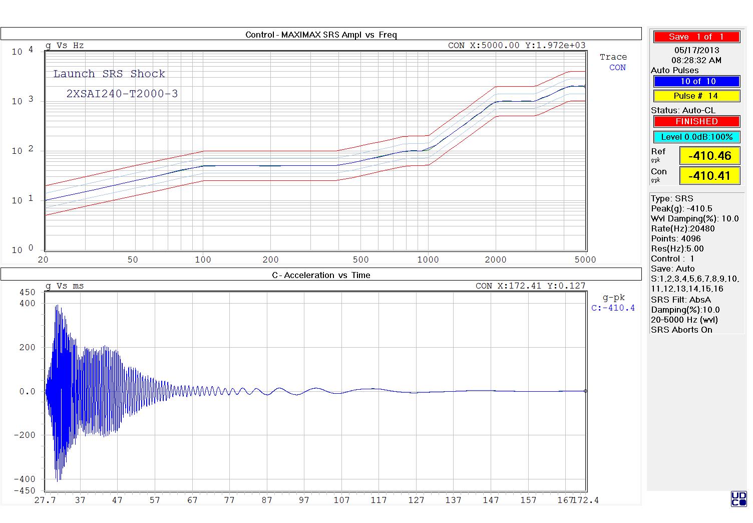
SRS Shock Specifications
- Up to 512 SRS Breakpoints (frequency / amplitude points or slope)
- Automatic Iterative Generation of Wavelets, including Frequencies, Polarity, Number of Half-cycles, Delay, and Amplitude
- Edit Mode Provides for Customization of Wavelet Parameters
- Maximax, Positive or Negative Primary
- Up to 100 Wavelets
- 1 Hz (min), 10 kHz (max) SRS Control
- SRS Frequencies - Wavelet Frequencies or Octave Spacing 1/n (n = 1 to 24)
- Damping of 0 to 25% (Q = 2 to 50)
- Display Time Waveforms, FFT, SRS, Ratio Spectra
- Measurement of Te and TE as defined in Mil-Std 810g
- Narrow SRS Pulse Selection for Adjusting TE and Te
- Extended SRS Waveform option available (Damped Sine & Burst Random Waveforms)
- Individual Channel Aborts
Sine on Random Specifications
- Includes General Features of Sine and Random Tests
- Up to 12 Tones on Random (Harmonic or Non-harmonic)
- Swept or Fixed Tones
- Digital Tracking Filter for Each Tone
- Shaped Reference for Each Sweeping Tone (Accel, Vel, Displ, and Sloped Segments)
- Manual Operation to Increase/Decrease Level and Enable/Disable Selected Tone(s)
- Random rms and Individual Tone(s), Amplitude(s) and Frequency(s) Continuously Updated
- Separate Sine and Random Spectrum Display for Valid Test Verification
- Selectable Combined Sine & Random PSD Display for Response Channels
- Gunfire Selection of Tone on/off Period
- Wide Frequency Range to 5,000 Hz
- Level Scheduling

Random on Random Specifications
- All Features of Random Tests
- Up to 12 Narrow Sweeping Bands
- Harmonic or Non-Harmonic Bands
- Complex Shaped Narrow Bands now Available
- Automatic Calculation of Harmonic Narrow Bandwidths and Swept Bandwidths
- Flat or Shaped Base band
- Minimum 1 Hz Narrow Bandwidth
- Minimum 2 Hz Sweep Band
- Sweep Times up to 99 Minutes
- Level Scheduling
- DC Voltmeter (up to 7 inputs) optionally available
- Mil-std 810 testing

TRAC Specifications
- Time Domain Control (Replicate Time Signal)
- Closed Loop Real Time Control with Continuously Updated Transfer Function
- Long Duration Reference (60+ Minutes at 1.024KHz sampling)
- Utilize DATAcq Saved Data or Other User Acquired Field Data (ASCII File) As Reference
- Looping and Cycling of All or Part of Waveform for Thousands of Hours of Testing
- Sequences of Multiple Unique Reference Waveforms
- Manual Selection of Level and Time Segment(s)
- Display Full Time Waveform & Zoom (1/8 - 4X Frame Time)
- FFT Analysis of Zoomed Range
- DC Voltmeter (up to 7 inputs) optionally available
