
Shaker Selection Criteria
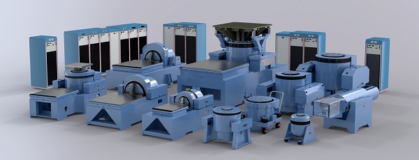 Unholtz-Dickie offers over 85 different vibration system configurations. Many of these systems cover "mainstream" testing applications, but a significant number are supplied for more specialized requirements involving extreme shock & vibration levels, high velocity, long stroke and other more demanding performance conditions.
UD has a staff of technically competent application engineers who are available during the system selection process and after the system has been installed and is in service. These application engineers are a key ingredient in UD's commitment to supplying the proper system for the job, with no surprises. Take advantage of this benefit.
Some of the fundamental technical considerations for system selection are reviewed below.
Force = Mass x Acceleration (F = MA)
In general, the selection of a vibration system requires application of Newton’s Second Law of Motion: Force = Mass x Acceleration (F = MA). But this basic formula is only a starting point. It may be instructive to describe one example of an incorrect approach to estimating the required system force rating.
Example: “I have a 50 lb test specimen that must be tested @ 10 g. Therefore, I need a vibration system rated at 50 x 10 = 500 lbs force.”
After reviewing the following technical discussion you will have a better understanding of why this estimate of system force is incorrect.
System Force Rating
Vibration systems have output force ratings typically expressed in terms of:
- Sine force: lbs (kN) pk
- Random Force: lbs (kN) rms
- Shock Force: lbs (kN) pk
The stated random force rating assumes a certain spectrum shape (usually flat) over a given frequency range (usually 20 Hz – 2,000 Hz) and a certain minimum mass load on the shaker. If these conditions are different from your test requirements, a new calculation of the effective random force rating may be necessary. These output force ratings provide a starting point for the Force (F) parameter in F = MA.
Mass
The mass value (M) in the initial F = MA force calculation must include all of the moving masses involved in the actual test setup: (shaker armature + test specimen + test fixture + any specialized adapters such as a Head Expander or a Slip Plate with its Driver Bar). Getting the right mass (M) value for the initial F = MA force calculation may be different for vertical axis testing compared to horizontal axis testing. Ask a UD applications engineer to confirm that the mass figure used accounts for all of the various components needed for your test.
As the frequency range of the vibration test increases, it is safe to assume that some or all of the mass components included in the estimate of (M) above do not actually behave as “masses.” Every mechanical structure has a resonant frequency, which may result in a significant dynamic force absorber effect at certain frequencies. This effect, which must be taken into account as part of the overall force estimating process, increases the F = MA calculated value of force.
Acceleration
The maximum Acceleration figure for the F = MA estimate is taken from the test specification, for sine vibration (g pk), for random vibration (g rms) and for classical shock pulses (g pk).
Two important factors related to the (g) level given in the test specification include the resulting maximum velocity and maximum displacement (stroke) required for your test. The velocity and stroke requirements are sometimes overlooked, leading to a poor system choice. Ask a UD applications engineer to review these important velocity and stroke calculations.
Streamlined Selection Process
The preceding review of factors that determine required System Force Output helps to illustrate that many variables are involved in the final, correct selection. As part of your discussions with a UD applications engineer, some or all of the following information will be helpful in order to streamline the selection process:
Product Details
- Product description
- Product test weight
- Product dimensions
- Product center of gravity (CG)
- Product mounting considerations
Fixtures
- Do they exist or will they require design and fabrication?
- Approximate weight (estimate if necessary)
- Approximate dimensions (estimate if necessary)
- Mounting issues
- Sizing issues
- Head expanders
Test Requirements
- Test types:
- Sine
- Resonance dwell
- Random
- Shock
- SRS shock
- Mixed mode (Sine on Random, Random on Random)
- Time replication
- Test magnitude
- Test frequency range
- Test duration
- Three axis testing requirement
- Product orientation with respect to gravity
Combined Environment Testing
- Ambient only
- Combined vibration / thermal testing conditions
Future Considerations
- Change in product line
- Requirement changes
Expandability
- Higher level test requirements
- Multiple product testing for reduced test time