What is an Induct-A-Ring Shaker?
 Some History
Conventional electrodynamic (ED) shakers use the same basic design configuration as a loud speaker – an AC voice coil suspended in a DC magnetic field that’s driven by an audio amplifier to produce vibration (sound). All conventional ED shaker designs have used this basic design configuration – just beefed up to industrial strength proportions. Therefore, most of today’s conventional shakers use a multi-turn wound armature coil (air-cooled or sometimes water-cooled) which interacts with a fixed DC magnetic field (produced by field coils) to develop output force when the driven armature coil receives AC current from a power amplifier.
This “moving driver coil” design philosophy completely dominated ED shaker development up until about 1970, when two important things happened.
- First, UD engineers developed a line of solid state (low-voltage/high-current) power amplifiers that soon replaced the earlier high-voltage/ low-current vacuum tube amplifier designs.
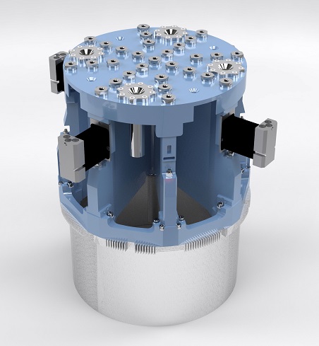
- Then, in concert with the new power amplifier development, Unholtz-Dickie engineers came up with a break-through shaker design that moved the driven AC coil from its original position on the moving armature frame to a stationary location within the ED shaker iron structure, but closely surrounding the bottom half of the moving armature. The lower section of the armature was changed to a solid metal, single-turn coil made from an aluminum forging.
In this performance modified shaker design, the power amplifier delivers AC current to the relocated stationary driver coils (called stators). These stator coils then induce AC voltages into the single turn armature ring they surround. This inductive coupling action produces AC currents in the armature ring, thus delivering AC force output at the moving armature.
This armature design was named “Induct-A-Ring” and was put into production by UD in the early 1970s. Since then, over 1,000 UD Induct-A-Ring Shakers have been built and installed in labs worldwide.
Since that time the UD Induct-A-Ring shaker family has grown into a formidable lineup of Vibration Test Systems rated from 15,000 lbf to 55,000 lbf (67 kN - 245 kN) and now available with up to 3" (76 mm) pk-pk stroke.
What You Get with Wound Coil Armatures
Conventional shakers utilize a wound coil assembly attached to the lower frame of the moving armature, and provide reliable performance for routine, low acceleration testing. In many high-performance shakers, the power amplifier must deliver 1,000+ amperes of AC current to this moving coil to generate rated AC force output. A conventional driver coil winding is typically made with hollow tubular wire that must be water-cooled to achieve sufficient heat transfer to cool the armature coil. As a result, this “wound coil” configuration requires a high current carrying linkage between the moving coil and the stationary shaker body, and also flexible hose linkages to deliver cooling water in and out of the coil.
At low frequencies, both of these linkages (current and water) are flexed up to the full stroke rating of the shaker. And at higher frequencies they are subjected to large accelerations (high g inputs) that can occur at the resonant frequencies of these linkages. Current linkages and water cooling hose assemblies are the proverbial “Achilles Heel” of a wound coil armature, and are the cause of many armature failures.
Also, the wound driver coil consists of multiple turns of wire held together with many epoxy joints. These epoxy joints are potential failure sites due to fatiguing of the joints or voltage breakdown (shorting) between adjacent wires. To remain within the temperature limits of the epoxy, the coil temperatures must be kept under approximately 250° F (121° C).
What You Get with a UD Induct-A-Ring Armature
The UD Induct-A-Ring armature utilizes a solid metal cylinder (ring) as the moving coil, with approximately 0.5 inch (12.7 mm) wall thickness. The force-generating AC currents in the IAR single turn coil are produced by induction, thus eliminating the need for current-carrying linkages between the armature and the shaker body.
Zero voltage operation
The solid metal ring has uniformly distributed electrical properties along its circumference. When induction occurs, any unit length along the ring has a voltage induced in it that’s proportional to the length of that segment. That same conductive segment has an electrical impedance (Z) that’s proportional to its length. The distributed voltages (E) summed along the length of the ring’s circumference produce a current flow in the single turn ring. But keep in mind that the voltage potential between any two points on the ring’s circumference is equal to the induced voltage rise minus the IZ drop that occurs when the induced current flows in that same segment.
The end result is this: The net voltage on the Induct-A-Ring coil itself is ZERO at all times, even at full shaker output – hence a zero voltage armature coil. This extremely important design factor means that the armature ring requires no electrical insulation from ground, and since all the current is conducted by the 1-piece ring, the need for epoxy-bonded coil wires is eliminated. With no electrical insulation or epoxy joints to worry about, the current carrying areas of the ring can be operated at 600° F (315° C). The resulting high surface temperature of the ring actually becomes an advantage, allowing extremely effective heat transfer with simple forced air cooling – thus eliminating the water hoses and fittings required by conventional wound coil armatures.
| Induct-A-Ring vs Conventional Armature Design | ||
|---|---|---|
| UD T2000 Induct-A-Ring | Conventional Shaker Design | |
| Armature Construction |  Solid metal, forged aluminum ring bolted to upper casting. |
 Insulated copper wire is held together with epoxy joints. Armature is epoxy bonded to upper casting. |
| Electrical Connection | Inductively coupled – No electrical current leads required. All points on moving armature remain at ground potential. | Fragile 1000 Amp current connection bridging shaker suspension required. Armature is at high voltage potential. Voltage break down and shorting (arcing) are possible. |
| Armature Cooling | Air-cooled – simple and effective | Design requires fragile water connection to bridge the armature suspension to cool the coil. These hoses and fittings are subjected to high vibration stress. |
| Armature Weight | 100 lb (45 Kg) moving element. Solid metal construction and reduced weight provide superior strength to weight ratio, a key factor for high performance and reliability. | >125 lbs (57 Kg) moving element (typical). Many individual components, potentially weak epoxy joints and non-rigid structures. |
| Rated Acceleration | 200 g sine / 600 g shock | 100 - 150 g max sine |
| Rated Stroke | 2 inches pk-pk (51 mm) 3 inches (76 mm) optional |
1.5 to 2 inches pk-pk (38 - 51 mm) - max |
In summary, how do Induct-A-Ring shakers improve the state-of-the-art? These shakers:
- Eliminate the need for current and cooling water linkages to the armature.
- Greatly improve the armature’s mechanical ruggedness by using a 1-piece solid metal driver
- Eliminate any voltage potential between the armature and the shaker body.
- Increase armature acceleration limits to 200 g pk Sine, 170 g rms Random and 600 g pk Classical Shock Pulse
- Provide significantly higher armature resonant frequencies (Fn) than wound coils designs. (i.e. 2,200 Hz for the 25,000 lbf (111 kN) T2000 IAR Armature and 2,000 Hz for the 40,000 lbf (178 kN) T4000 IAR Armature)
